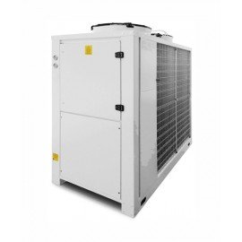
SIGA CSHENRF-160
Availability:
Description:
The range includes models that cover a refrigeration capacity ranging from 1 to 1500 kW. Compact chillers are for outdoor installation. The range has been designed for use both in the process and comfort sectors. The machines are equipped with all the components that ensure automatic cooling of water or a water/glycol solution. To guarantee maximum operating safety the units have (or can have) two completely independent refrigeration circuits. All units are supplied with a full oil and refrigerant load after having been factory tested. The chillers are divided in two product ranges: chillers with scroll compressors and chillers with screw compressors. For scrolls refrigerants used are R407C/R410A/R404A, while for screw compressors refrigerants are R407C/R134a/R404A. Models where scroll compressors are used are installed with shell and tube evaporators or plates evaporators (or coaxials). Models with screw compressors are installed with shell and tube evaporators, with optional opportunity of high efficiency evaporators for R134a refrigerant, which reach energetic Class A.
Options:
|
1.0 MECHANICAL CONFIGURATION |
3.0 REFRIGERANT CIRCUIT CONFIGURATION (drawing code n. ) |
|||||||
|
LNJ Low noise version (RV included) |
LW Low water temperature until -10°C outlet (RC, RV, thicker insulation included) |
|||||||
|
ATS Spring type antivibrant mounting |
CSV Compressor valve |
|||||||
|
CV Epoxy coated condenser coil |
4.0 ELECTRIC CIRCUIT CONFIGURATION |
|||||||
|
CF Condenser filter |
OFC On-off compressors signal |
|||||||
|
CG Condenser treatment (blygold) |
OFR Remote control (on/off) |
|||||||
|
2.0 HYDRIC CIRCUIT CONFIGURATION (drawing code n. ) |
OFRC Remote control display with on/off remote+alarm management, Carel microchiller2 (IP54) |
|||||||
|
SS.T Tank in stainless steel with coaxial evap.SS/Cu (std open type-closed type on request) |
RS485 Serial card for modbus RS485 |
|||||||
|
SS B-ES. Tank in stainless steel with plate evaporator (std open type-closed type on request) |
RVG Volt-metric relay (CSF included) |
|||||||
|
DP3 Double P3 pump (valve betwwen tank and pump included) |
RC Cranckase heater |
|||||||
|
PH P5 Pump |
SF Soft start |
|||||||
|
DP5 Double P5 pump (valve betwwen tank and pump included) |
IRC Compressor inverter |
|||||||
|
BPA Automatic by pass until 50% of the flow rate |
EC EC fans |
|||||||
|
XV Expansion vessel kit available for closed-type tank |
PLW Plantwatch PRO |
|||||||
|
LLA Electronic low level alarm |
PLV Plantvisor |
|||||||
|
VTP Valve between tank and pump |
||||||||
|
NT.NP Without tank and without pump, with shell and tube evaporator |
||||||||
Technical Specification:
|
Cooling CSHENRF FREE COOLING |
Model |
070 |
075 |
090 |
100 |
130 |
160 |
|
|
NOMINAL COOLING CAPACITY (1) |
kW |
70 |
75 |
87 |
102 |
118 |
150 |
|
|
NOMINAL COOLING CAPACITY (1) |
Frig/h |
60200 |
64500 |
74820 |
87720 |
101480 |
129000 |
|
|
TOTAL COMPRESSORS NOMINAL ABSORBED POWER |
kW |
18,2 |
21,4 |
25,0 |
28,0 |
33,7 |
43,3 |
|
|
(1) |
kW/kW |
3,84 |
3,50 |
3,48 |
3,64 |
3,50 |
3,47 |
|
|
COP |
kW/kW |
3,17 |
2,97 |
2,82 |
3,02 |
2,84 |
2,83 |
|
|
EER |
4,5 |
4,4 |
4,3 |
4,5 |
4,2 |
4,4 |
||
|
ESEER |
5,0 |
4,9 |
4,7 |
5,0 |
4,7 |
4,8 |
||
|
IPLV |
C |
2 |
2 |
2 |
2 |
2 |
1 |
|
|
AIR TEMPERATURE 100% FREE COOLING (2) |
nr. |
2 |
2 |
2 |
2 |
4 |
4 |
|
|
REFRIGERATING CIRCUITS |
nr. |
1 |
1 |
1 |
1 |
2 |
2 |
|
|
PARTITION STEP |
nr. |
1 |
1 |
1 |
1 |
1 |
1 |
|
|
REFRIGERANT |
R410A |
R410A |
R410A |
R410A |
R410A |
R410A |
||
|
HYDRAULIC SECTION |
|
|
|
|
|
|
||
|
NOMINAL WATER FLOW |
m3/h |
12,0 |
12,9 |
15,0 |
17,5 |
20,3 |
25,8 |
|
|
EVAPORATOR PRESSURE DROP (4) |
kPa |
33 |
26 |
42 |
58 |
66 |
78 |
|
|
FREE COOLING PRESSURE DROP (5) |
kPa |
63,0 |
60,0 |
85,0 |
112,0 |
121,0 |
120,0 |
|
|
AVAILABLE PRESSURE |
mca |
23,5 |
23,8 |
21,2 |
18,2 |
21,1 |
20,7 |
|
|
MAXIMUM PUMP ABSORBED POWER |
P3 |
kW |
3,46 |
3,46 |
3,46 |
3,46 |
6,12 |
6,12 |
|
MAXIMUM PUMP ABSORBED CURRENT |
A |
6,33 |
6,33 |
6,33 |
6,33 |
10,40 |
10,40 |
|
|
AVAILABLE PRESSURE |
mca |
44,0 |
56,0 |
53,0 |
49,0 |
46,0 |
45,0 |
|
|
MAXIMUM PUMP ABSORBED POWER |
P5 |
kW |
6,12 |
8,30 |
8,30 |
8,30 |
12,04 |
12,04 |
|
MAXIMUM PUMP ABSORBED CURRENT |
A |
10,4 |
14,1 |
14,1 |
14,1 |
20,2 |
20,2 |
|
|
HYDRAULIC CONNECTIONS |
BSP/DN |
2" |
2" |
2" |
2" |
DN65 |
DN65 |
|
|
TANK VOLUME |
dm3 |
410 |
410 |
410 |
410 |
390 |
390 |
|
|
FAN SECTION (AXIAL) |
|
|
|
|
|
|
||
|
TOTAL AIR FLOW |
m3/h |
36000 |
36000 |
49500 |
54000 |
66000 |
72000 |
|
|
FANS |
nr. |
2 |
2 |
3 |
3 |
4 |
5 |
|
|
FANS ABSORBED POWER |
kW |
3,88 |
3,88 |
5,82 |
5,82 |
7,76 |
9,70 |
|
|
FANS ABSORBED CURRENT |
A |
7,80 |
7,80 |
11,70 |
11,70 |
15,60 |
19,50 |
|
|
TOTAL ELECTRIC DATA |
IP |
IP54 |
IP54 |
IP54 |
IP54 |
IP54 |
IP54 |
|
|
NOMINAL ABSORBED POWER (6) |
kW |
25,6 |
28,7 |
34,3 |
37,3 |
47,6 |
59,1 |
|
|
MAXIMUM ABSORBED CURRENT(F.L.A.) (6) |
A |
57,8 |
63,1 |
78,0 |
84,5 |
102,9 |
127,8 |
|
|
MAXIMUM PEAK CURRENT (L.R.A.) (6) |
A |
173,4 |
178,6 |
222,0 |
273,0 |
201,7 |
243,3 |
|
|
ELECTRIC FEED |
V/Ph/Hz |
400/3/50 |
400/3/50 |
400/3/50 |
400/3/50 |
400/3/50 |
400/3/50 |
|
|
NOISE DATA |
|
|
|
|
|
|
||
|
SOUND PRESSURE (3) (6) |
dB(A) |
59,2 |
59,3 |
60,8 |
61,4 |
61,8 |
62,9 |
|
|
DIMENSIONS AND WEIGHT |
|
|
|
|
|
|
||
|
LENGTH |
mm |
3355 |
3355 |
3355 |
4355 |
4355 |
5350 |
|
|
WIDTH |
mm |
1105 |
1105 |
1105 |
1105 |
1105 |
1105 |
|
|
HEIGHT |
mm |
2180 |
2180 |
2180 |
2180 |
2180 |
2180 |
|
|
WEIGHT EMPTY |
kg |
1460 |
1470 |
1510 |
2100 |
2200 |
2420 |
|
|
WEIGHT OPERATIVE |
kg |
1930 |
1940 |
1980 |
2800 |
2900 |
3120 |
|
Data referred to: |
||||||||
|
(1) Inlet/Outlet water temperature = +12/+7 °C - Condenser air temperature = +35°C; fouling factor = 0.000043 m²K/W |
||||||||
|
(2) Inlet/outlet water temperature = +12/+7 °C |
||||||||
|
(3) Sound pressure level referred to measures according to normative ISO3744, pressure level at distance of 10 m, referred to free field on reflecting surface |
||||||||
|
(4) Evaporator + valve + piping pressure drop (no free cooling) |
||||||||
|
(5) Free cooling coil + evaporator + valve + piping pressure drop |
||||||||
|
(6) Data referred to standard configuration WP (with pump P3) |
||||||||

